Sunday, April 25, 2021

Happy Anniversary!!!!!

 Its amazing how fast time flies.  I can hardly believe its been a year since I started this project.  Before I provide my update, I want to do a 'Then and Now' reflection.  I'm amazed at the progress I've made and I can actually see light at the end of the tunnel.  The only part on the car I haven't touched is the bonnet and that is because it doesn't need much work.  If life would stop interrupting my fun, I could finish this project. 

My original goal was to complete it in a year but now with that date past, I will try to complete it before the Oil Leak tour in October.  Oil Leak, you question?  It is an annual event where a group of fellow British car lovers get together for a week and see some of the sights our great country has to offer.  Its a really low key trip with people who not only like to restore their cars but drive them too.

Anyway, here are some Then and Now Pictures:

I brought home a rust ridden, multi-piece ready for the scrap yard car


Now, its rust free and one piece.  It is beginning to resemble its original design.  No longer is it destined for the scrap heap.  It has a bright future ahead of it


Before putting these pictures together, I've not really reflected on just how much work I've done over the past year.  When I started this project, I estimated about 1000 manhours to complete it and I think I'm still on target for that or maybe just under.  I've probably spent 600 hours on it so far and have done most of the hard work.  I still have to spend some quality time with the doors but can't do that until I get all the chrome back.  

Now, for some more progress pictures:

I just mentioned getting the chrome back.  It took awhile but it is starting to get done.  There were a few pieces I sent off, they declined to chrome or gave me the option to just replace instead.  So far, the pieces they didn't want to do are readily available and probably cheaper than I could repair/ rechrome.  Of the remaining pieces, the one I am most concerned with looking good, is the grill.  From the very beginning, I was concerned about a missing fin.  I found a very nice thread on jaglovers xk120 Grill Project where a guy made brand new ones and I was prepared to do the same.  Miraculously, the missing fin was among the parts I sent to be chromed so I don't have to make it now.

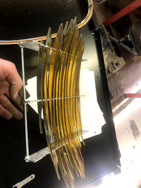
As others had mentioned, the chrome shop recommended disassembling the grill for stripping and polishing.  They said I could do it as one piece but the sides of the fins would not get polished and therefore would not look like new.  Taking their advice, they gave me back the grill and I unsoldered all the fins.  This was not very difficult as they are not brazed in and a propane torch worked quite well.  Propane isn't hot enough to effect the brass plating.  By removing the fins, I could also replace 2 of the studs that broke when I pulled the grill from the bonnet.  Those I brazed back in so they would be stronger than just solder.

Have I mentioned how nice it is to have access to a mill?  There is no way I would have been able to tackle this project otherwise.  Taking a que from the jaglovers thread, I made a jig to hold the fins.  To ensure the grooves were identical, I drilled guide holes in each piece, bolted them together and then milled out the grooves.  Since the grill has an arch, I made each one a different height so the fin could rest in it while I soldered them in.

Grill fin holder

A quick check to ensure the fins fit properly

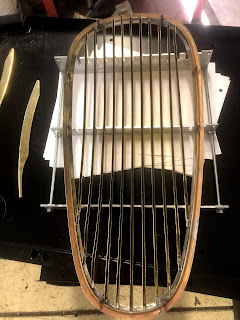
This was presolder.  I inserted all the fins so I could make sure the frame was centered with the fins


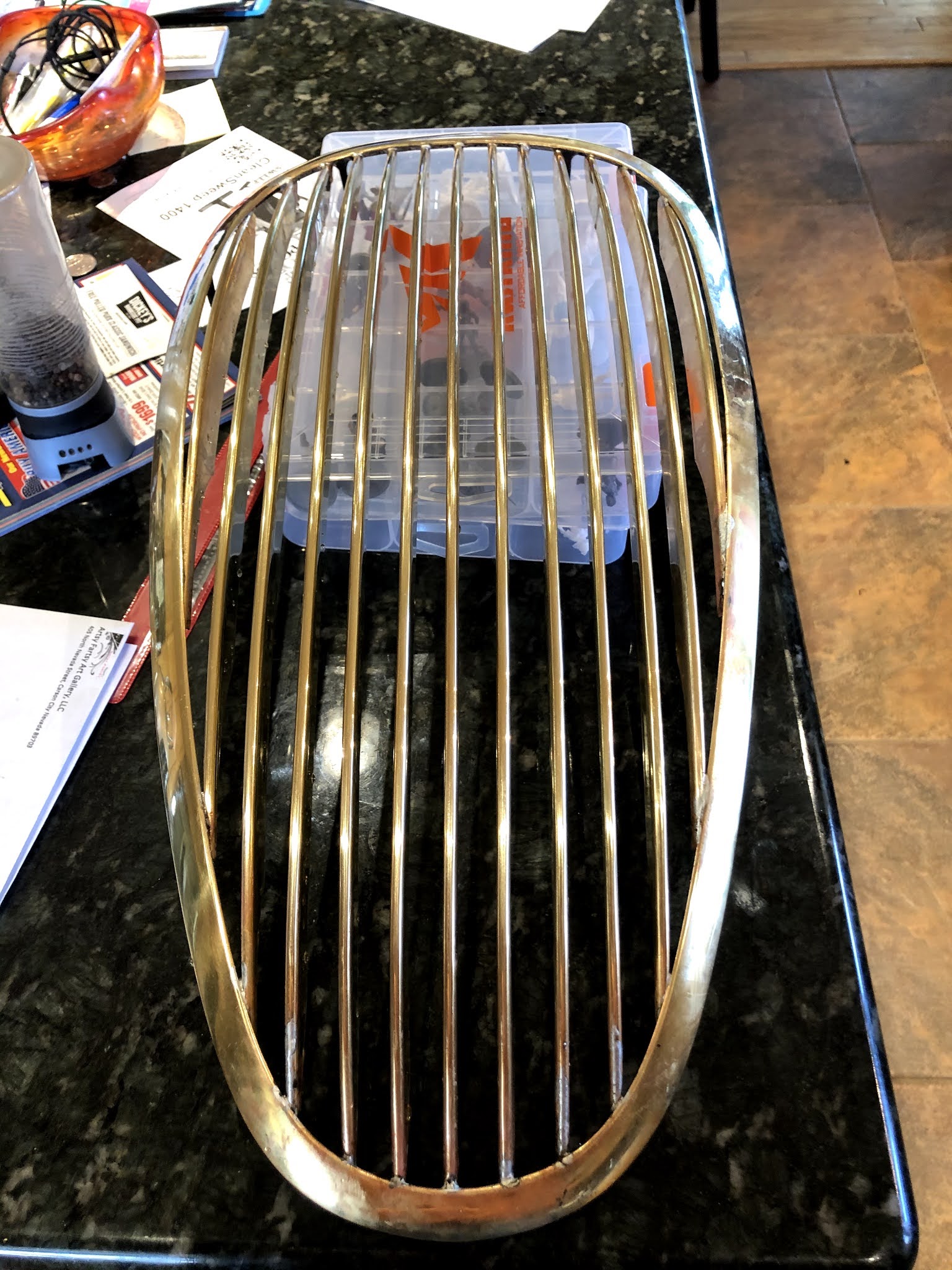
And after all the fins were soldered in.  The chrome shop has already plated everything in brass and polished it.  Once they get this back, they just need to do one final polish and the nickel/ chrome plating. 

To make sure I wasn't going to have an issue when I went to mount a newly chromed grill, I did a test fit.  Fit right into place, I'm very excited about it.

After a long hiatus, I decided to get back to some of the remaining body work.  My initial focus was on the boot section, posts and sills.  Once those were complete and the car back together, I turned my focus to the frame and mechanicals.  Now that I'm continually in holding patterns, waiting for parts, I've filled my time with the bonnet section.

When I had the body sand blasted, it revealed all the areas I expected and a few I didn't.  One area I didn't expect was the fender mounted signal lights.  They were extremely pitted on the sides and as I found, completely rusted out underneath.  Obviously, this is what happens when things are added as afterthoughts, instead of designed in.  

To start, I wanted to remove the lead filler.  This would help me locate the new pieces, as well as help me see how best to remove the old ones without damaging the fenders.(not sure why, there turned out to not be much fender left).  Once I removed the old signal holders, I could really inspect the damage.  From underneath, the 'hole' for the light almost seemed purposeful but it turns out, it was just the shape of the signal light from the rust.

What I discovered is the light holder was affixed to the top of the fender and the only hole was the wiring pass through at the rear.  With the forward tilted fender, any dirt, grime and moisture that found its way into the cavity was destined to remain there for the rest of its life or until it ate a hole through the fender so it could get out.  I am drilling a hole at each front corner to try and prevent this from happening in the future.

Before removing the fixture, I made X-Y alignment marks so I could place the new one in the correct location.  From there, it was just cut, shape and replace.
With the light housing removed, I found that almost the entire fender underneath was gone.  I probably could have just welded the new one on top and none the wiser but really??  I've done this much, might as well do it right.

The passenger side wasn't as bad but still bad

This was a test fit before grinding down all the welds underneath


Same for the other side.  You can see my alignment marks to ensure I put the new one back in the same location

First, I tacked each on in place and then went back and seam welded them

Not the final picture but close.  Now, the only spot left to replace is the lower edge of the bonnet nose on the driver's side. 

And here is the final picture with all the welding and grinding done.  Just a little feathering with some body filler required.  

Another project I tackled was the bonnet hinges.  At first glance, I thought these hinges had already been restored.  They looked fairly clean but did seem a little stiff.  I thought maybe they were just stiff by design so I installed them.  I discovered they are NOT stiff by design.  Even after risking damaging the bonnet by open and closing the hood a few times did not help loosed them up.  Thanks to Bob, Bob's Hinge, I decided to do the same.
Old vs. New
The left is the factory version, the left will be the final design.  I used stainless tubes for the spacers, copper washers between each moving part and stainless screws & nuts.  Like Bob, I'm making these black instead of the factory gray finish.  I think they will stand out better with the white color.

One final thing for this update is the wood dash.  As opposed to the hinges, the wood is actually in better shape than it looked at first glance.  The lacquer has not aged well but the burled wood is mostly in good shape.  The only piece that isn't great is the dash side panels.  Having a friend who is a woodworker, he thinks he can relaminate the wood on new backing.  If not, this is probably the easiest piece to replace.
Here is the wood pieces.  If you look, you can see the delamination on the left panel.  I sanded the glovebox lid to see what it looked like under the lacquer.  It looks pretty good, there is a section at the bottom edge that will need a little creative painting to hide but think my wife, the artist can do it.

Next post will HOPEFULLY include the first crank of the engine and maybe the fuel injection.  Stay tuned.

Saturday, February 20, 2021

XK120 Fuel Injection & oil pump

I'm going to consider this post more of an interlude than an update.  I do continue to make progress but it has been slowed because I have been waiting for parts.  When I started the project, I sorted parts by mechanical, body, interior and electrical.  I started with the body and am now making my way through the mechanical.  Not that it was my original intent but ultimately, I'm making a bit of a hybrid (some might say a bastard) car.  If I were to start over today, I might do it slightly different but I am where I am.

In my last post, I talked about my struggles using a different set of main bearing caps and that I was having a hard time getting the oil pump drive to line up.  Having made a wedge spacer, I was OK with the alignment but not the spacing.  

If you look at the left side of the photo, you can see the wedge spacer I spent quite a bit of time sizing.  More important though is the gap between the drive and the drive gear in the bottom right.

Since I was waiting to get the oil pan back from the machine shop (more on that later), I had time to think about my oil pump setup.  The more I thought about it the more I didn't like it.  To do it the right way, I knew what I needed to do but I was quite frankly scared to do it.  While, I'm not sure exactly how the angle from engine to engine could vary that much, the way to fix my issue would be to machine my main cap to the correct angle.  Not having the proper alignment tools and not wanting to spend days shaving a few '000s off at a time, what could I do?

*******We interrupt this regularly scheduled blog to bring you a message from our sponsor (not), 3D printers.  For anyone who has seen an ad for a 3D printer and thought to themselves, "I'd like to have one of those.", get one.  If you have been reading my blogs, you might recall a 3D rendering of my Fuel Injection system.  When I decided to design my own system, I bought a 3D printer so I could print my prototypes before paying someone to machine them only to discover my measurements were wrong.  I have used a 3D printer to make mock ups of every piece I've designed so far.  Saved me hundreds, if not thousands of $$.  If you consider yourself an inventor and have a small amount of computer skills, you can buy a 3D printer for <$300 and download all the software you need for free.  Now back to our regularly scheduled program.**********

Having a pretty good starting point for the angle I need, I decided the safest thing to do was print a main bearing cap.  Using my real one as a guide, I was able to draw and print one out fairly quickly (except for the 19hrs it took to actually print it).

My printed cap was the correct dimensions but I did have to hog out a section for the oil pump drive but the angle was really close.  A few minutes with some sandpaper and I got the drive to line up very well.  Now, I feel much better about milling off the surface of my main cap.

Using the printed cap, I was able to ensure the surface was 90 degrees from the drive gear.  Having this, I could angle the cap properly in the mill to reproduce the same angle.


You can see it under the baffle plate but I had to rebend the discharge tube because the angle of the pump changed enough to make the other one useless.  Speaking of baffle plate, I had to make that too and the oil pickup.  The pickup is not quite aligned here but ultimately, it will be flat with the pan.  It isn't free floating like the factory pickup but it will do the trick.

Here is the top down (or bottom up) view of the pickup and the baffle plate.  Not having any oil pump tubes (but 3 pumps) and not wanting to fabricate a pickup, I found one online that was close to what I wanted and just welded it to the end of my fabricated pickup tube.

Can't quite see it here but another fabrication I had to make was weld ears onto the front Main bearing so the baffle could bolt somewhere.  Does the customizing ever end?????


I had to fabricate the rear baffle plate that attaches to the pan.  Thanks to forums.jag-lovers.com for some great reference pictures.  View from the front of the pan showing the front mount.

Well, after 15-20 hours of fabrication and rework, I feel much better about my oil pump.  On to the next project.

Speaking of oil pans, what happens when you try to use a later model timing cover with an older model oil pan?  Answer: A trip to the machine shop.  I discussed this issue in my previous post but having decided to modify the later model timing cover to work with my period correct engine resulted in having to modify the oil pan too.  I discovered that a rope seal uses a slightly smaller diameter seal groove than a rubber seal (1/8").  Thankfully, having the correct size timing cover gave me something to give the machinist as a guide.
Not quite like the factory did it but having read somewhere that Jaguar actually machined the front lip off (the timing cover) to make changing the seal easier, I told the machinist to just worry about the diameter and not the lip.  Time will tell but the I am very happy with the result.

 With the front seal worked out and the baffles made, I just need to receive the oil pump o-rings and I can button up the bottom of the motor.  Never order something you really need with a low or out of stock item.  The vendor will hold the order until complete.  I think I'll order another set so I can wrap this up and test the engine.

Speaking of testing the engine, I've spent quite a bit of time working on my fuel injection since my last post.  While 3D printing parts I've designed helped me ensure they fit, when installed, it didn't help with maintenance parts.  I mentioned last time that I couldn't remove the valve covers using the XK150 water rail and would have to fabricate my own water rail.  Well here it is.

Hot off the mill.  I used a 2"x3" square aluminum so there would be enough room to use the Jag thermostat housing - far right of the picture.

With this design, I am able to remove the valve cover without taking everything apart.  Here you can see the thermostat housing attached to the front end.


As one last test, back in the car to see how everything works out.  Uh-oh, two problems.  

The radiator mount goes where I put the air box.  This is easily remedied in my final design, won't affect my dyno testing.  

Second problem, I removed the T-stat housing because it barely clears the radiator.  There is NO WAY a hose will connect between the rail and radiator.  Back to the drawing board.

 
I don't have it on the motor yet but doing some research online, I found some inline T-stats that I contemplated but felt like temperature control might be difficult.  I liked the design and concept so just made my own.  Not only did I make my own but I welded aluminum for the 1st time too.  Still need to clean everything up but I'm pretty happy with my work.


You can see from here, I cut the front of the water rail flush with the front water outlet from the head.  Welded my T-stat directly to the front of the rail.

The connection will be at a slightly different angle but should be very close to the factory connection.  I'll have to wait for the hose kit to arrive to be sure.
 
In addition to the mechanics, I have most of the electrical complete too.  All I need to finish is wiring in the O2 sensor and its ready to test.

Since I was spending time at the machine shop, I made the standoff for the tooth wheel at the same time.  Using my 3D printer once again, I designed the mounts for the timing pickup.  I missed the length by a little bit but that is easy to fix.  Change the design and press 'Print'.

Next post should include pictures of the interior and back to the body work.  Things are coming together.  Now, if I could just get the rear hubs of the axle, I could have the wheels back under the frame.


Wednesday, January 6, 2021

Why does it take so long to do the little things?

Its been just over a month since my last update.  With holidays and such, I haven't been able to spend as much time in the garage as I'd like. 


Over the last several weeks, most of my accomplishments have been on the little things.  It also seems it doesn't take me long to change my mind.  My last post I said I was not going to paint anything until after I test fit everything.  Before I fit anything, I went ahead and painted the front suspension.  After thinking about it, I decided it would be better to paint the suspension before I installed bushings and such.  After receiving the bushings, I am regretting my decision.  I ordered Urethane bushings and they don't get pressed in so I could have painted everything later.  As it turns out, I might be painting again anyway.  At minimum, I'll have to touch up a few spots.

The engine came back from the builder, finally.  It looks really good and I can't wait to fire it up.  Builder says adapting the new main caps to the block wasn't too bad.  


Having the engine back, I can now address my next hurdle.  You might recall, I acquired 2 engine blocks with the car.  One a period correct W block and the other a later V block.  Not really thinking about what could change in 4-5 years of production, I decided to use the W block.  Well, now I know most of the parts I have were for the V block and parts are hard to find.  

What is different you ask?  The later V block has a hydraulic tensioner instead of a pressure blade type.  The change required a redesign of the front cover and I haven't been able to find the correct cover so what do you do?  You make one.
As you can see from my template, the later model cover extends out more than the earlier.  Fortunately, its basically just a single mount that needs relocated.

First step was to cut out the offending section and weld the mount in the correct location.  I mounted the cover to ensure the mount was right before attaching it.

Next, I used the pieces I cut out to fill most of the holes created.  This way, all I (well OK, the welder that works for me) had to do was minor fill work.

I have to do a little work on it but it turned out looking really nice.  Once on the engine, it will be hard to distinguish it from a real one.  Additionally, the later one uses a rubber seal instead of rope.  This creates another problem though, the oil pan will have to be modified too.  More on that in a later post.

I'll make a big reveal here.  This is unconfirmed information but I believe this will be the first EFI port injected, EDIS XK120.  System designed by 'me'.

I started this design on my E-type but testing on this engine means I can still drive my E.  Once the bugs are worked out, I will install on the E too.

Here is my original design that I am having to modify.  In this version I planned on using the XK150 water rail but I didn't leave enough room to pull the valve cover off.  This doesn't work well for a Jag so I am designing my own water rail.  That too is for a later post.

View from the top

View from the side

Before finalizing the design, I am going to do some dyno testing.  For that, I need to be able to adjust the length and size of the runners.  Once the design is established, Everything will be set.

Angle view

Top view

I don't want to finish the body work until mounting the body back on the frame, there is still some work to catch up on.  Having worked through most of the body alignment I'm confident I'm not taking the fenders back off. Time to finish welding them back together.


Since I painted all the front suspension parts, I might as well see how it all fits back together.  The bushing kit arrived as well as the Wilwood front disc brake kit.

First order of business is to size the steering connector rod.  Another part I was missing and all I could find was one for an MK sedan.  It has a wider wheel base so the rod is too wide.  After doing some research I found that the rod is just a hollow pipe, threaded on both ends.  It should be no problem to cut it down and reweld it.

To ensure the ends remained square, I used a piece of channel.  Then, I clamped the ends straight and tacked it back together.

Until I mount the idler arm and steering rod I won't know for sure but should be close enough to adjust with the tie rods.  I'll wait to finish the welds until I have it all together.

New hubs and Wilwood calipers look fantastic.

One last thing for this post is the oil pump.  Here is another moment of clarity.  This one I knew about but expected the transition to be easier.  Since I didn't have the original main caps and the ones I used are the later model which is good because they use the more readily available top mounted pump but...
I discovered that apparently, the pump mounted is also engine specific.  To align the pump with the drive, I had to create a wedge shim.  What I did was insert a 3/8" drive socket extension in the square drive and measure the angle.  I then measured the thickness required for the pump to be at 90 degress to the drive.

With the pump mounted, I could then fabricate my own oil pick up tubes.  Right now, without the oil pan, I can only make the outlet.  Since I'm using the larger oil pump from an E-Type, I can run a full 3/4" tube discharge.  Hopefully this will help with oil flow/ pressure.


Coming up in my next post, I'll install the motor back on the frame to check for spacing on the air box.  I think I have enough space with my current design but it doesn't hurt to be sure.  One thing I still have to work out is where to locate the MAF sensor.  I thought I could mount it directly to the throttle body and use the factory air ducts in the fender.  Right now, it is not working out that way.

I also hope to have more of the EFI design installed.  Currently waiting for the oil pan to return.  This will allow me to install the timing cover and thus the harmonic balancer.  On front of the balancer will be the toothed wheel and timing pickup.  I can then finish the wiring.