Four weeks into this project and I'm accomplishing more than I thought I would at this point. Part of my progress I owe to COVID-19. Depending on when you're reading this, it might be a major pandemic or the farse of 2020, time will tell. Anyway, I digress.
This week I continued........RUST removal (how strange). Having received the frame rails last week and mounting them, I'm getting really anxious to try them out. After extensive reading, I have been convinced I need to mount the whole body on the frame before permanently welding anything together. Since the rear fender mounts are either rusted away or have broken studs are completely unusable. If I'm going to align the fenders and shut panels with the doors and rails, I have to work on the fender mounts.
 |
| As you can see, the rust is BAD. There is supposed to be a bolt at the top of this picture but its gone. I took this picture after cutting out the piece. I cut down the inside edge so everything will be hidden upon final assembly. I measured 2" in from there and cut from the center all the way to the back end |
 |
| Another shot of the underside of the fender mount looking at the taillight section |
 |
| Here is the same view as the first pic with the rust section cutout. The area to the left of the cutout isn't more rust, its undercoating. This will not be fun to remove. I think I'm going to have to get it out before I send the body out for blasting. |
 |
| Interesting, it seems Jaguar must have negotiated a great price on 18ga steel. After cutting out the rust, I discovered there is two layers of metal. One layer has the captive nuts and the other is the actual inner fender panel. |
 |
| Since all the nuts were either rusted or seized, I need new ones. Since no one is going to see them when I'm done, they don't need to be perfect. I was able to salvage one to use as a model, I made a few more. Not perfect but functional. I found some 5/16-24 square nuts at McMaster. The weldable ones looked just like originals |
 |
| Here is the finished nut panel. |
 |
| Here is another view of the back end. I pulled the spacing of the nuts by laying the panel over the fender and marking bolt locations. |
Having spent almost a whole day working on the inner fender and the fender itself. Maybe pictures of that later. I needed a break from welding so I turned my focus back to the hinges and doors. I again neglected to take as many pictures as I should have so I'll have to explain what I did.
When removing the hinge boxes, like most people restoring these, I discovered the hinge bolts were seized in the hinges. To get them out, I cut the bolts off even with the hinge box and drilled down far enough to free the hinges. Once the hinges were out, I was able to heat them with a torch and drive the remnants of the bolts out of the hinges.
Next step was to press in new bushings and hinge pins. I wanted to stick with the 5/16" diameter pin so bought some 3/8"OD x 5/16"ID bushings, once again from McMaster. In addition, I bought some flange bushings too. They were 7/16"OD x 5/16"ID.
 |
| Since the flanged bushings are thicker than the hinge box, I am adding some steel stock to make sure everything is tight. |
 |
| Here is a picture of the hinge pin |
 |
| More about the screw sticking out of the hinge later, thats on a different picture. The purpose here is to show the hinge box opened to 7/16" to receive the flanged bushing |
 |
| As promised, more on the screw or more apropos, all thread. This may have been overkill but I read many warnings about hinges not being aligned and the door binding up. To make sure they are aligned, I ran a 5/16" all thread all the way through and tightened the steel stock pieces with the flanges to the top and bottom of each hinge. |
 |
| In addition, I clamped a reinforced flat bar to the hinge plate faces to ensure free movement. After comfortable with movement, I welded the steel spacers to the hinge plate and removed the all thread. |
 |
| These cars were hand built so no too were the same. Because of this. all the XK experts will tell you to take measurements of sill height, number of spacers, cowl location, firewall height/ location, etc before taking the car apart. Its impossible to do that if you buy the car already apart. Fortunately, the PO did it (at some point). I spent several hours taking measurements and making adjustments until everything matched. |
 |
| Just to appease myself, I put the floor panels in just to see how everything fit. Panel mounting holes line up and if you look closely, the rear of the panels are aligned. Just waiting for the rear half to be installed. |
 |
| Next step was installing the doors to see how they fit. I hope but I doubt I will ever leave such useful information behind for someone else. I'll just leave 50 plastic totes full of unmarked parts for someone to sort through. It is still possible because I've done one of those projects too. Takes a lot longer when you have to figure out what a part is prior to knowing where to install it. |
 |
| OMG, the door FREELY opens and closes AND clears the sill. Not perfect yet but very encouraging. The driver side isn't quite as nice but still not bad. The driver's door frame needs some attention so I think there's more of issue with it then the hinge panel |
 |
| Not bad door gaps without trying. I think I'll be able to make them look good. The door hinges are very solid with minimal slack so once I get them set they will stay that way. |
 |
| Further motivation, its starting to look kind of like a car. Part of me wants to install the floor pans back in, seats and steering just so I can really get the car vibe. Either way, small victories keep me motivated to keep going. |
 |
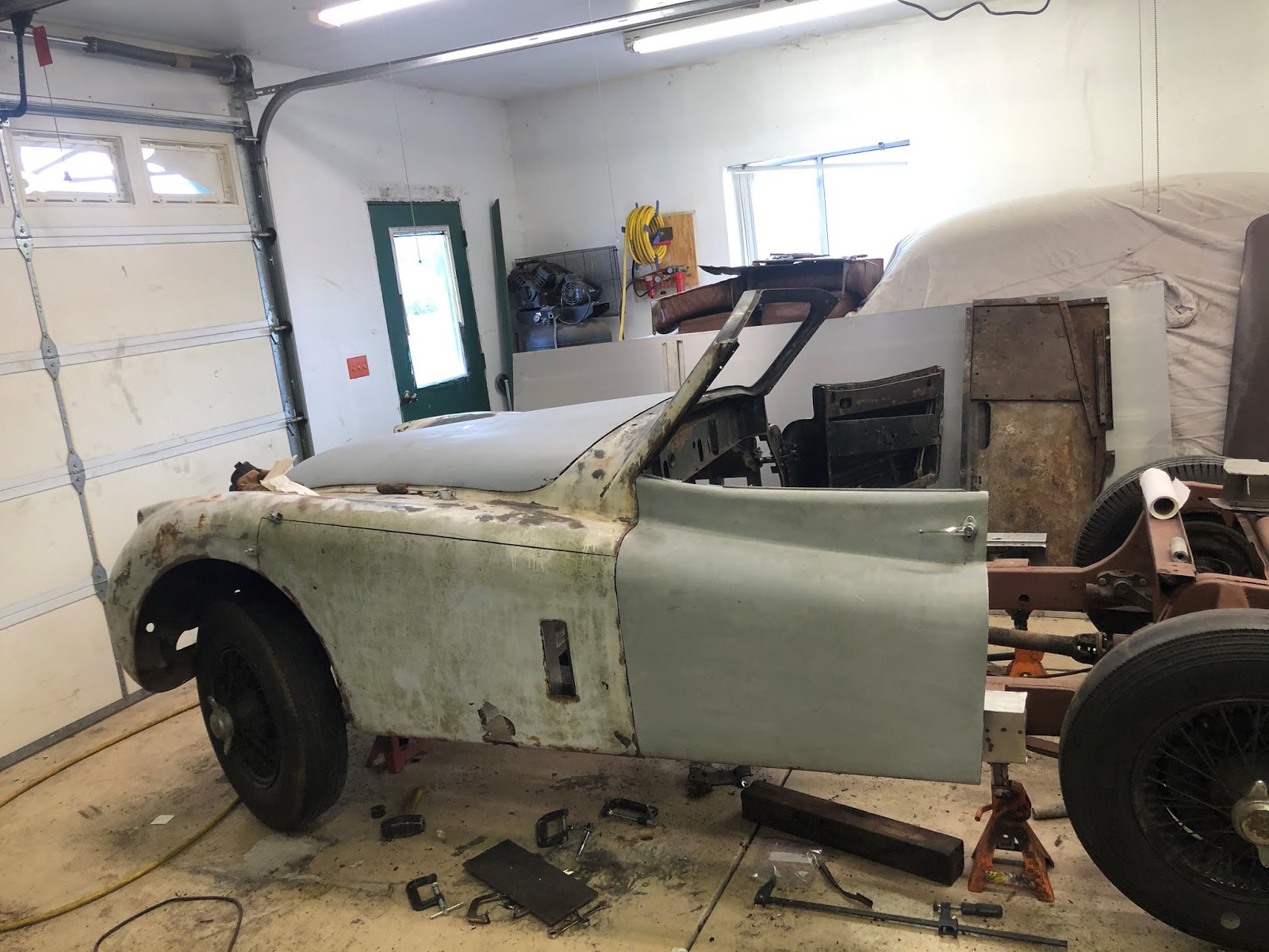
| Side view with doors installed |
After mounting the body and ensuring everything was aligned according to the sketch I found, I was very excited to install the doors. They fit fairly well but the top edge of the door was crashing into the windshield pillar. A little bit discouraging to think you've done everything right and it not be quite there. I expected to have to add or delete shims but with the correct gap at the top of the door, I didn't see how that would help. After thinking about it, I began to suspect the dash panel wasn't aligned with the cowl support and hinge box. This would be a big job and virtually starting over. This would be a job for next week.
Or so I though. Feeling dejected, I went in the house and then I had an epiphany. When measuring the alignment of the body to the frame, there was one measurement that I made some assumptions. The measurement in question was tie rod to frame (16-1/2"). The sketch showed the measurement from the center down to the frame. When I took my measurement, I was getting 17-1/2" but I noticed the tie rod is kicked up on each end so I thought maybe the measurement was from the tie rod mounting hole, not tie rod itself.
With the door crashing into the cowl at the top and thinking about the assumed measurement origin, I decided to take another look. Upon further examination, I realized the fender connecting plate (the bonnet latch plate that ties the fenders together) at the front slides under a piece of metal and bolts to the plate underneath. When I mounted the body, I rested it on top of the metal, not underneath. Not knowing where it was supposed to go, I assumed it had to go on top because the body wouldn't go down further. This was because there was a 3/8" thick plate welded to the bottom of the frame. I don't know why its there and have no one to ask. With it removed, I was able to slide the front down where it is supposed to be. Now the measurement from the center of the tie rod to the frame is exactly what it is supposed to be. Making this change, the doors no longer crash into the windshield. There is still a slight alignment issue but not top to bottom, its front to back. The top of the door protrudes out slight from the cowl. I have some ideas but that will wait until next week.
 |
| I don't know how the body actually fit on the frame with this piece of steel mounted underneath. Makes it really seem like a tractor frame not a car. A few minutes with a cutting torch and its gone. |
 |
| Before calling it a weekend, I decided to cut out the rusted metal on the other side of the rear body. Same processes as the other side. Cut from the inside edge of the fender lip and 2" in front to back. |
 |
| Here is the view with the rust cut out. I have to make a few more captive nut holders and then weld this side up. I think then I'll be able to mount the rear on the frame and then it WILL look like an XK120. I expect that to be next week and then off to the sandblaster. |